Although the majority of popular compact-disc players on the market offer 16-bit x4 times oversampling, it is by no means certain that this is the standard for the future. Philips-Valvo have introduced new decoding chips that may herald the third generation compact-disc player offering 1-bit x256 times oversampling.
Figure 1 of Pitch Control for CD Players showed the block schematic of a typical second -generation compact-disc player. The signal processing (decoding) section of that diagram is repeated in Fig. 1 of this article. It consists of four special CD ICs and a standard DRAM. For the third -generation CD player, the four special CD ICs -have been replaced by two new ICs as shown in Fie. 2. The current Philips SAA7220 is a phase linear, 4x oversampling digital filter with 120 filter coefficients. Its frequency response is shown in Fig. 3. In conjunction with the Type Philips TDA1541 16 -bit digital-analogue converter and the Type Philips TDA1542 third -order analogue filter, it has a ripple of only 0.02 dB in the pass band and an attenuation of >50 dB outside the pass -band. It is not ideal for use with de -emphasis circuits. The Philips SAA7220 also interpolates the values of missing or uncorrectable samples. It can estimate up to eight such samples as shown in fig. 4. The figure also shows that the Philips SAA7210 decoder provides a basic interpolation function prior to the Philips SAA7220.
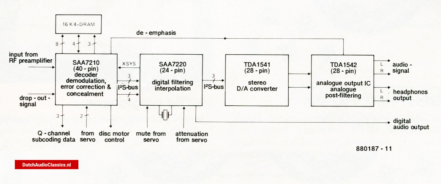 Fig. 1 - Block diagram of the decoder and digital-to-analogue converter in a typical second-generation cdplayer
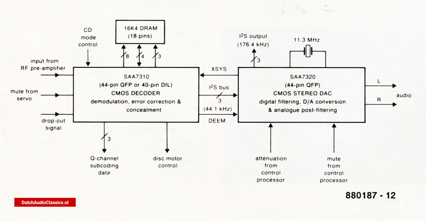 Fig. 2 - Block diagram of the decorder and digital-to-analogue converter stages in a third-generation cdplayer: five chips have been reduced to three.
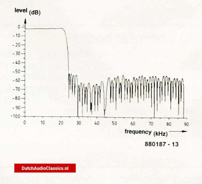 Fig. 3 - Frequency response of the digital filter in the Philips SAA7220
For good sound quality, both efficient error correction and good linearity of the Type Philips TDA1541 digital -to -analogue converter are vital. This IC contains two complete 16 -bit D -A converters that, like the earlier Philips TDA1540, operate on the well-known current division principle. Since each of the stereo channels has its own converter, there is no time delay between their signals. The conversion time is shorter than 2μs, so that data rates of more than 6 Mbit/s can be processed. By periodic overlapping of the two D -As on one chip, it is possible to achieve a sampling rate of 380 kHz per channel. As a matter of fact, in some CD players the Philips TDAI541 provides 16 -bit x 8 times oversampling.
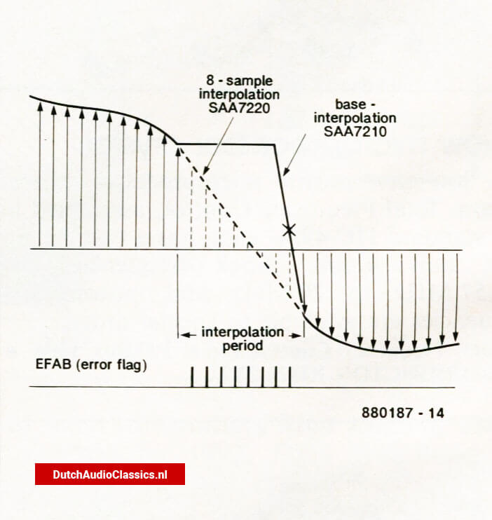 Fig. 4 - The Philips SAA7220 provides basic interpolation of uncorrectable sample values. The Philips SAA7220 then equalizes up to 8 sequentail sample values by linear interpolation
The Philips SAA7220 is connected to the Philips TDA1541 via a so-called I2S (Inter-IC-Sound) bus. This consists of a clock line, a serial data line, a control line, and a line that connects the system clock in the Philips SAA7220 to the Philips SAA7210 (where the clock is connected to the disc motor servo). The control line serves to indicate whether the data pertain to the left-hand or right-hand channel. The Type Philips TDA1542 third -order low-pass filter also has provision for a matching amplifier and a driver stage for headphones output.
The internal circuit of the Philips TDA1542 and the external components required to form it into a Thomson -Butterworth third -order low-pass filter are shown in Fig. 5. Its frequency response is shown in Fig. 6. Without de -emphasis, the cutoff frequency is about 45 kHz, so that in the CD transmission range up to 20 kHz ripple and phase shift are very small. When the sound reproduction has de - emphasis, the Philips TDA1542 is provided by the Philips SAA7210 with an appropriate control signal that actuates the de -emphasis elements via opamps A2 and AT. The response is then as shown by the dashed line in Fig. 6. It has a number of lower cut-off frequencies which cause a noticeable phase shift. The equalizing characteristic and the equality of the two channels is then determined largely by the tolerance of the external resistors and capacitors, so that fairly large deviations from the nominal values may result. This fact is normally ignored during the testing of CD players. It would be interesting to see the frequency response of CD players that have de -emphasis. It must be admitted that there are not many of these, however. It is even so that, for instance, Cambridge Audio Systems have removed the de -emphasis circuits from their latest high -end CD player.
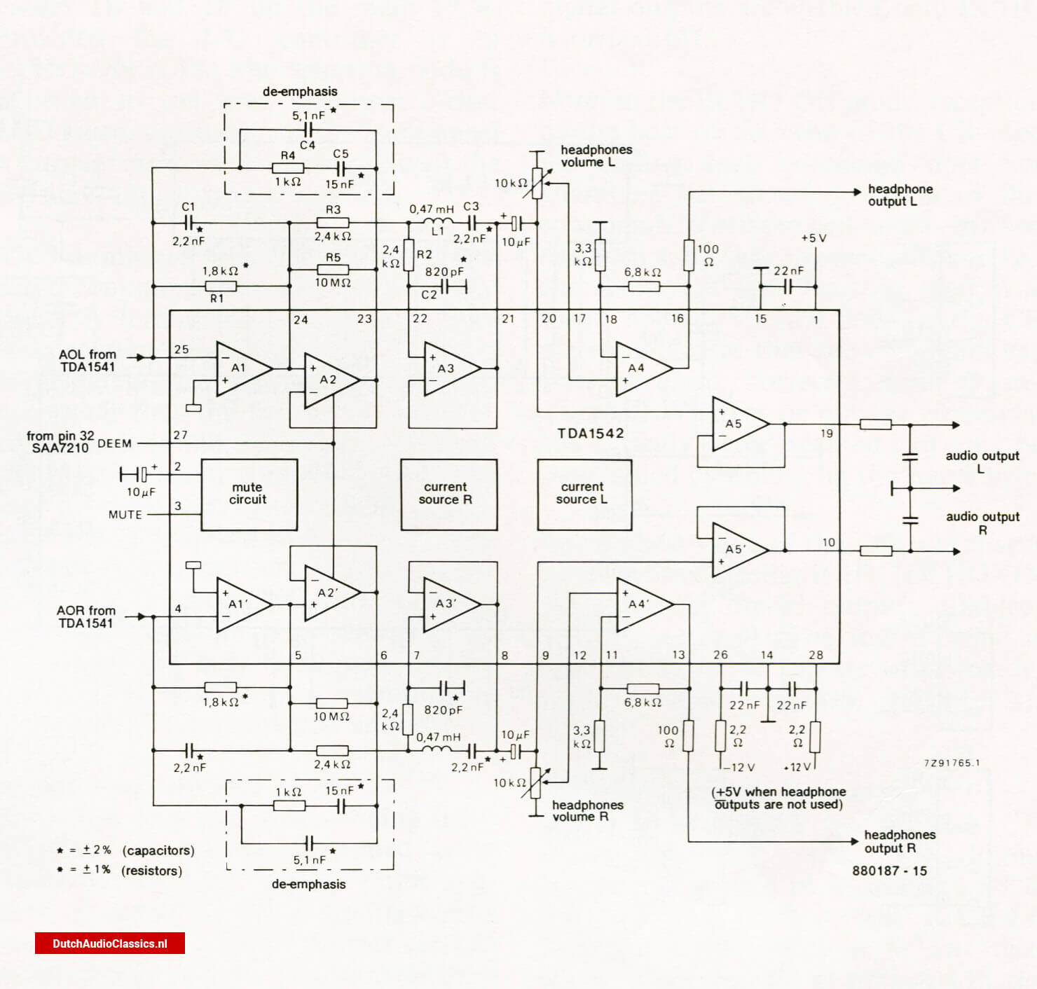 Fig. 5 - Internal circuit of the Philips TDA1542 together with the external components required to make it into a third-order low-pass filter.
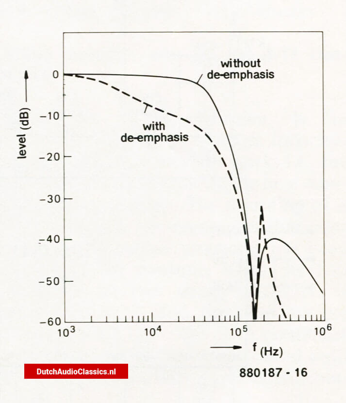 Fig. 6 - Transfer function of the filter in Fig. 5 with and without de-emphasis.
Network L1 -C3 forms a notch filter for appropriate attenuation of the 156.4 kHz harmonics at the output of the D -A converter. A complete circuit diagram of a typical decoder circuit found in many popular CD players is given in Fig. 7. Instead of the not yet widely used Philips TDA1541, two dual opamps Type NE5532 are used to form the analogue filter. The de -emphasis circuits are actuated by relay contacts Kl and K2. The relays are energized by driver T2 at the DEEM output of the Philips SAA7210. The stereo signal is available at outputs a and d. There is no provision for headphones outputs.
It is worth noting that in this circuit, as well as in that of Fig. 5, electrolytic capacitors are used in the signal path. This was also the case in the Philips CD players used for the research of this article. It only goes to show that if you don't know there are electrolytic capacitors in the signal path, you don't hear their presence! None the less, Walter Jung, who, as Matti Otala, became well known in the 1970s by his articles on a.f. opamps and amplifier techniques, gives his recommendations for reconstructing these circuits without the use of electrolytic capacitors in the January 1988 issue of The Audio Amateur.
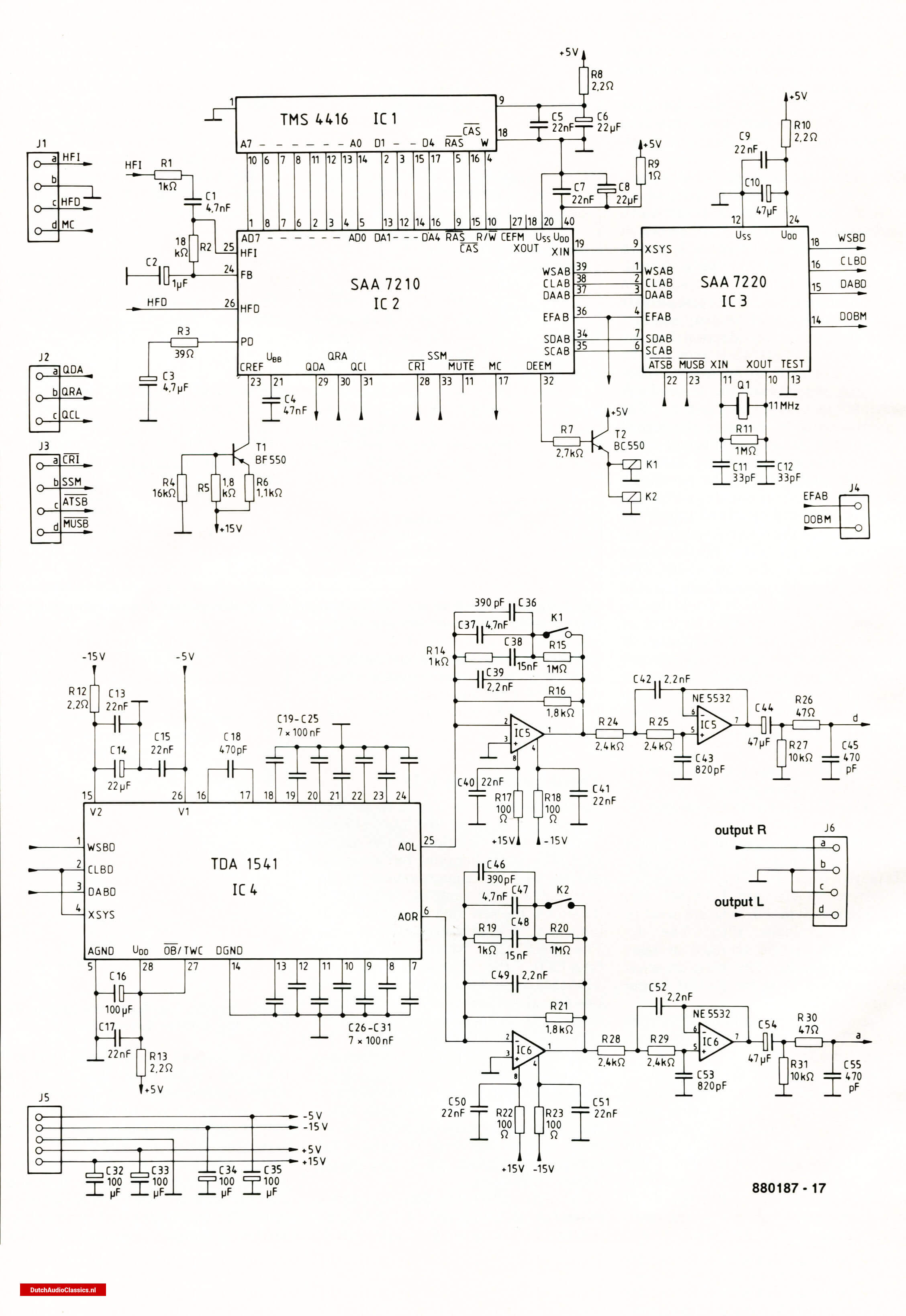 Fig. 7 - Circuit diagram of the decoder and digital-to-analogue converter stages in a typical second-generation cd player.
Third generation CD
As already shown in Fig. 2, in the next generation CD player, the Philips SAA7310 performs the same functions as the current Philips SAA7210: demodulation, full error correction, and basic interpolation of uncorrectable audio samples. In addition, it controls the new data interpolation inhibit and the data concealment process. The Philips SAA7320, which replaces the Philips SAA7220, the Philips TDA1541 and the Philips TDA1542, includes a phase linear digital low-pass filter, two newly designed high - linearity D -A converters and opamps for analogue post -filtering. Like the Philips SAA7220, it has facilities for attenuating the audio output by 12 dB, which can be used at the start of fast forward/fast reverse commands and a search for a track, for instance. In addition, the soft mute facility that can be used when moving to another track and during pauses is retained.
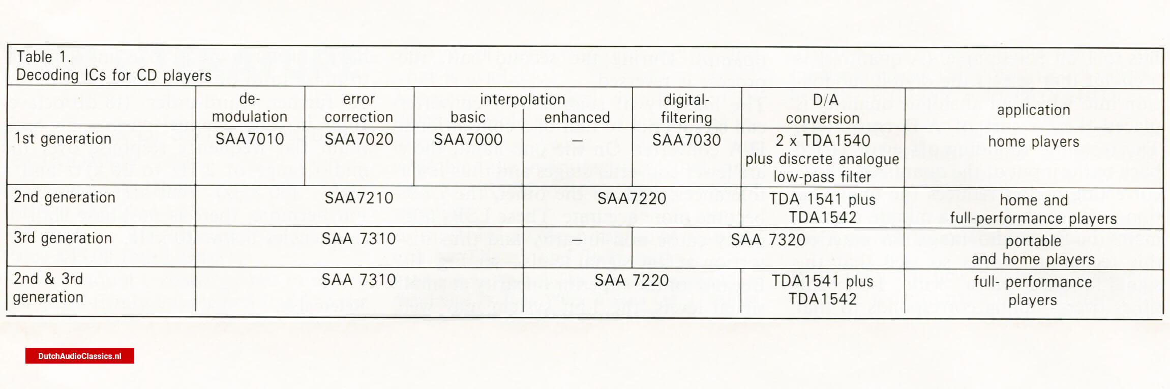 Decoding ICs for CD players overview
As already stated, the data format between the Philips SAA7310 and Philips SAA7320 is according to the inter -IC sound specification, 12S. The I2S bus is a 3 -line bus comprising clock, serial data line, and a control line used to select right-hand and left-hand channel words. The I2S format allows combinations of second- and third -generation ICs to be used in a CD player, giving the player manufacturer maximum design flexibility. Apart from having fewer ICs, the third - generation players draw a much smaller current, since the new chips are all made in CMOS technology and intended for surface mount production. The Philips SAA7310 is, however, also available in a DIL package. The new chips should, therefore, make possible the production of inexpensive, high -quality portable and mobile CD players. The possible combinations of current and new - generation chips are given in Table I.
The data flow in the Philips SAA7320 is given in block schematic form in Fig. 8. The first filter stage corresponds to that in the current Philips SAA7220, but has 128 filter coefficients instead of 120. The filter is followed by an I2S output so that operation with a Philips TDAI541 as D -A converter is possible. The remainder of the IC is then not used.
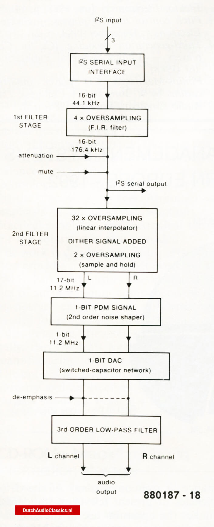 Fig. 8 - Block schematic of the data flow in an Philips SAA7320
The 4x oversampling filter is followed by a further oversampling filter (64x; first 32x by linear interpolation and the 2 x by sample -and -hold). An internallygenerated noise resembling dither signal is added to the signal to reduce quantization distortion at low sienal levels. This increases the amplitude, however, so that after interpolation 17 -bit wide samples ensue.
The 256 x oversampling process therefore provides 17 -bit words at a sampling frequency of 11.28 MHz (=191.76 Mbit/s). A 1 -bit quantizer reduces the 17 bits to 1 bit per sample. (A quantizer is a circuit that selects the digital subdivision into which an analogue quantity is placed, i.e., a sort of A -D converter). The resulting rounding -off error is fed back to the input of the quantizer, whose correcting action reduces the quantization noise so that only a minute part remains in the audio range. In practice, this technique works so well that the signal-to-noise ratio with I -bit x 256 times oversampling corresponds to that of a conventional 16 -bit D -A converter without oversampling.
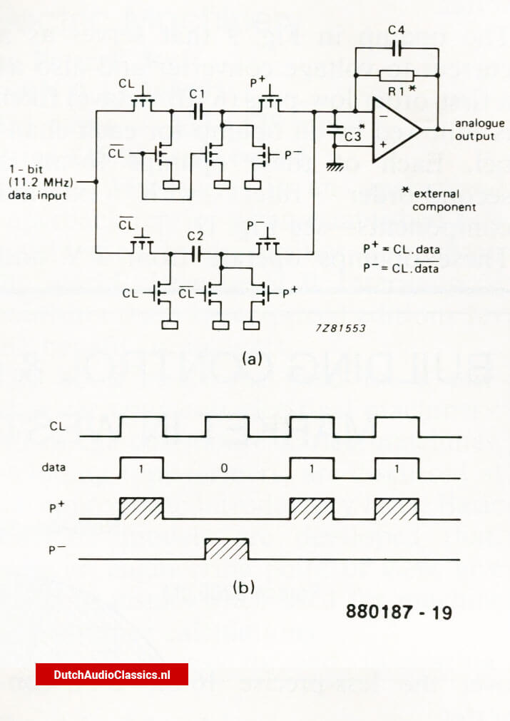 Fig. 10 - At low signal levels, the linearity of the 1-bit system is better tan that of a conventional 16-bit D/A converter
The actual 1 -bit D -A converter consistsof a very simple circuit with switched capacitors as shown in Fig. 9. During the first half of the sampling period, depending on the logic state of the data input, capacitor Cl is charged (drawing current from the inverting input of the opamp) or C2 discharges (sending current into the inverting input of the opamp). During the second half, the process is reversed.
The linearity of such a 1 -bit converter can be superior to that of a conventional D -A converter. On the one hand, there are fewer converter stages and thus fewer tolerances, and on the other, the LSBs become more accurate. These LSBs normally cause non -linearity and thus distortion at low signal levels-see Fig. 10. Because of the superior linearity at small signal levels, the 1 -bit system may well offer advantages (acoustically speaking) over the less -precise 16 -bit D -A converter.
Fig 11. - Schematic diagram of the decoder, D/A converter and analogue filter in a third-generation cd player. Compared with second-generation circuits, as in Fig. 7, it has far fewer components.
The opamp in Fig. 9 that serves as a current -to -voltage converter and also asa first -order low-pass (6 dB/octave) filter is followed by an opamp for each channel. Each of these opamps forms a second -order filter with external components-see Fig. 11.
These opamps operate from 5 V and have a slew rate of 30 V/ps and a signalto- noise ratio of more than 100 dB. A further, third -order (18 dB/octave) filter in each channel ensures an optimum flat frequency response over the audio range of 2 Hz to 20 kHz and a high (60 kHz) cut-off frequency. Furthermore, there is no phase shift at frequencies below 20 kHz.