April 1984
The sampling process which converts a digital audio signal from binary numbers back to its original analog form generates spurious frequencies, which must be filtered out of the final wave form. Most brands of Compact Disc players use analog filters for this, usually in a system consisting of a 16 -bit D/A converter, a sample -and -hold circuit, and an analog low-pass filter (Fig. 1).
Philips oversampling system for compact disc decoding
 Philips TDA1540 d/a convertor
 Fig. 1 - Analog output section of a CD player using only analog filtration.
This, however, can be difficult to do accurately. First, the D/A converter must be linear to within one-half the value of the least significant bit (LSB). However, '/2-LSB accuracy of the dividing steps becomes more and more difficult to achieve as the number of such steps, or bits, increases. For 16 -bit D/A converters, low yield and high cost can easily be obstacles to practical manufacture.
"By oversampling at fourtimes the original sampling frequency, the original noise energy is now spread over a band four times as wide."
A second problem is caused by analog filtering. A filter steep enough to adequately remove residual components above the audio band must inevitably be a complex one, degrading the signal accuracy and introducing phase distortion. Even an active lowpass filter has a large amount of phases shift near its cut off frequency. Such a filter also generates noise and requires high-speed operational amplifiers, which have high power dissipation and require tight component tolerances to maintain low ripple in their pass -band. Temperature changes and component aging of such filters also affect performance adversely.
Philips engineers have found a way to carry out most of the essential filtering process digitally. This approach is used in the players sold by Philips under its own name and under its U.S. brand names of Magnavox and Sylvania. It has also been adopted, in whole or in part, by some other manufacturers.The spurious frequencies to be removed are functions of the sampling frequency used in the digital process. If the quantized samples of the original audio frequencies are simply converted to analog values, a series of spikes is produced (Fig. 2A).
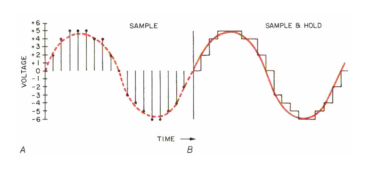 Fig. 2 - D/A converter outlines the desired waveform as a series of signal spikes (A), which are then extended by the sample-and-hold circuit to produce a staircase waveform (B).
The envelope of this series resembles the audio waveform, but the spikes, in reality, produce an infinite series of frequency bands at multiples of the sampling frequency (in this case, 44.1 kHz), as shown in the unshaded portions of Fig. 3.
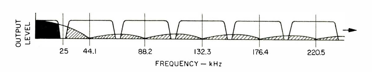 Fig. 3 - Spikes of Fig 2A produce an infinite of series of frequency bands centered on multiples of the sampling frequency (shown in outline). Sample-and-hold reduces out-of-band output (shades portions) but still leaves substantial output between 25 and 44.1 kHz and reduces audio high-frequency response (solid portion).
In practice, a sample-and-hold circuit holds the output voltage steady after each sampling spike until the next sample is decoded by the D/A converter. This converts the waveform from a series of spikes into a "staircase," as shown in Fig. 2B. This also has the effect of substantially reducing the frequency bands above 20 kHz. However, significant components still remain, particularly in the region between 25 and 44.1 kHz, as shown by the shaded portions of Fig. 3.
Note, too, the cut at the top of the audio band in Fig. 3. This cut occurs because the sample-and-hold process can be represented by a Sin X/X function, with the first zero point occurring at the sampling frequency, 44.1 kHz. Response compensation could be employed at the analog stage, but only at the expense of additional phase distortion and noise.
Philips uses a different circuit configuration for D/A conversion (Fig. 4), incorporating oversampling, digital filtering and noise shaping. Each plays a vital role in the filtering and conversion process.
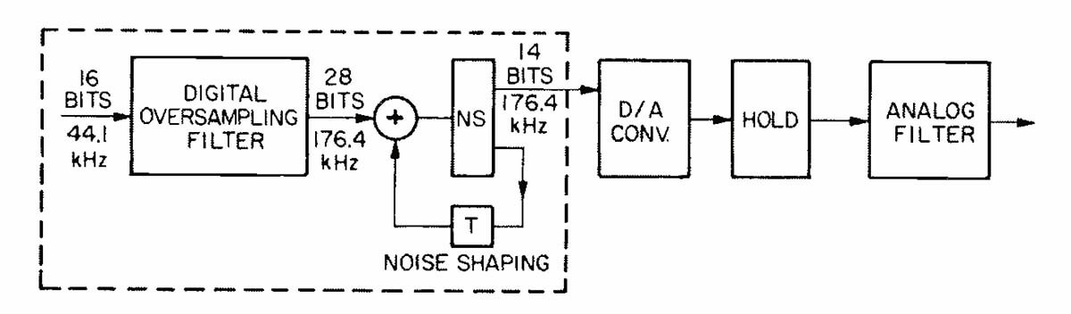 Fig. 4 - Analog output section of CD player using Philips system of oversampling, digital filtering, and noise shaping. Some analog filtration is still required.
Oversampling is accomplished by increasing the sampling frequency four times, to 176.4 kHz. This results in a frequency spectrum containing multiples of the original 44.1 -kHz sampling frequency, at 88.2, 132.3, 176.4 kHz and so on. By oversampling four times, the noise power originally restricted to a band from 0 Hz to 22 kHz is now distributed over a band four times as wide, or 0 Hz to 88 kHz. Only one -quarter of the noise remains within the audio band, and the rest will be eliminated by filtering, giving a 6 -dB improvement in performance.
Both the oversampling and much of the filtering take place in a digital transversal filter. The signal enters this filter as 16 -bit data at the 44.1 -kHz sampling rate, and leaves as 28 -bit data at a rate of 176.4 kHz.
"The full 16 -bit information capability of the Compact Disc is retained in this Philips system by transferring information to the 14 -bit level."
A transversal filter can be considered as a series of delay lines and multipliers whose outputs are summed. A theoretical transversal filter for CD would have 96 elements, as shown in Fig. 5. In this model, each 16 -bit sample is delayed for one-fourth thesp sampling period, and the output of each delay is multiplied by a 12 -bit -accurate coefficient; the product of each multiplication therefore has 28(16 + 12) bits. After these multiplications and a subsequent addition, the weighted average of a large number of samples is obtained.
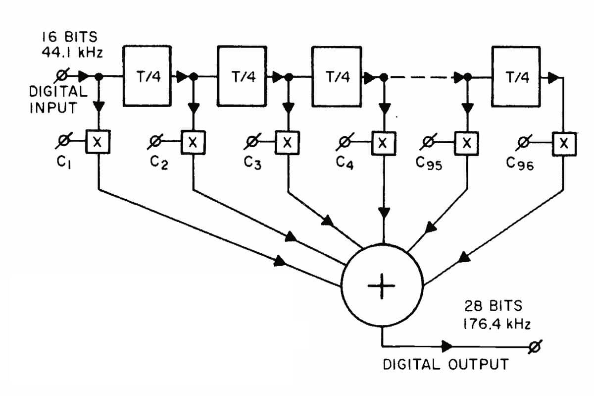 Fig. 5 - Theoretical 96 -element transversal filter. C1 through C96 are 12 -bit multiplication coefficients; T/4 is time delay of one-fourth sampling period (0.0000056 S).
However, since new data arrives at the filter input only once per sampling period, three out of four of the numbers multiplied in our theoretical filter would be zero. In practice, therefore, the filter is simplified to include only 24 elements, each with a delay equal to the entire sampling period. Each 16 -bit data word is then multiplied four times, with different coefficients for each multiplication, before being passed on to the next delay.
An immediate effect of the digitalt transversal filter is to suppress all the lower frequency bands, centered at 44.1, 88.2 and 132.3 kHz, as shown in Fig. 6. For the coefficients chosen, the filter has a transition region between 20 and 24.3 kHz (the sloping area in the solid block of Fig. 6) and, due to over -sampling, leaves the 20 -kHz side -bands on either side of 176.4 kHz.
 Fig. 6 - Digital transversal filter suppresses output between audio band (solid portion) and the band surrounding the oversampling frequency (176.4 kHz).
A further improvement in signal-to-noise ratio is obtained in the noise -shaping circuitry (Fig. 7). This rounds off the 28 -bit data from the transversal filter into 14 -bit data. The 14 least significant bits, which contain mostly quantization noise and round -off error, are then delayed by one sampling period, reversed in sign and summed with the next sample. This reduces the average quantization error and noise for low -frequency signals (audio) by 7dB. At high frequencies approaching half the sampling frequency, or 88.2kHz, the feedback becomes in phase with the input, and its noise increases. But since this out -of -band noise is filtered away, it is no longer relevant. There sulting noise spectrum is shown in Fig. 8.
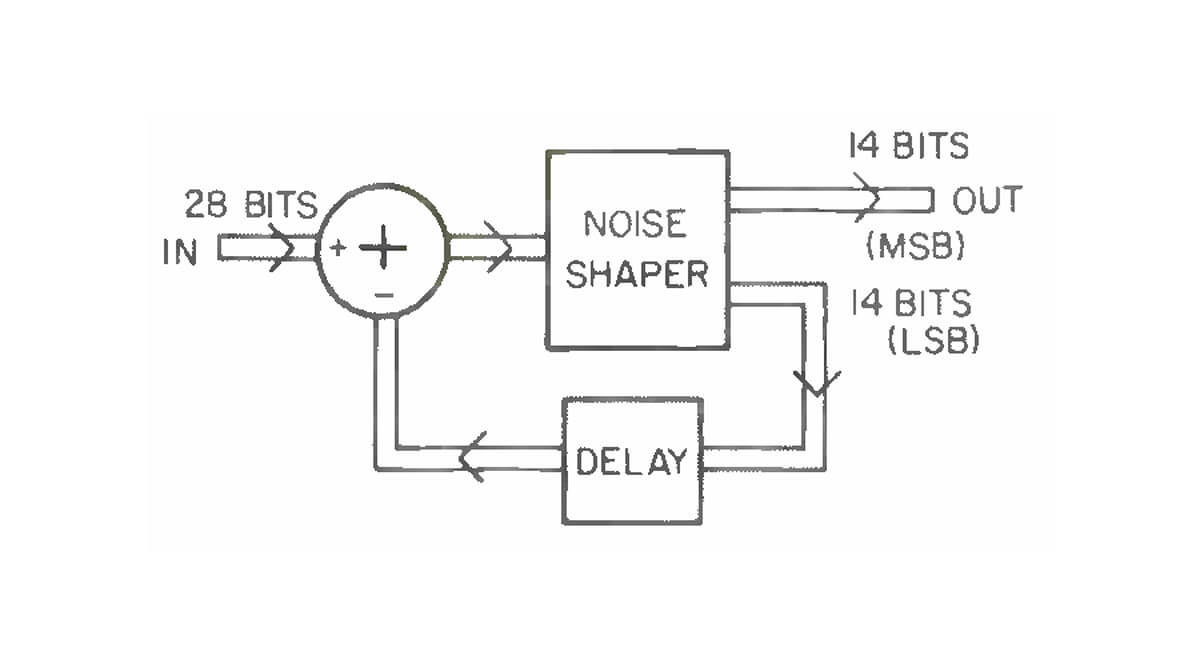 Fig. 7 -N Noise-shaping circuit (see text).
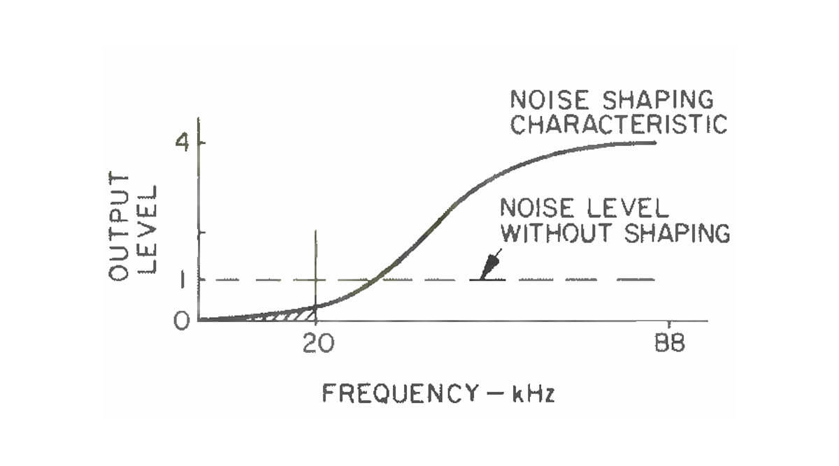 Fig. 8 - Noise spectrum after noise shaping.
Much of this filtering is accomplished by the sample -and -hold circuits, which modify the frequency spectrum with the Sin X/X response mentioned earlier (Fig. 10), such that a null occurs at 176.4 kHz and the side -bands on either side of that frequency are attenuated by more than 18 dB.(The hold effect causes no phase distortion in the audio band.)
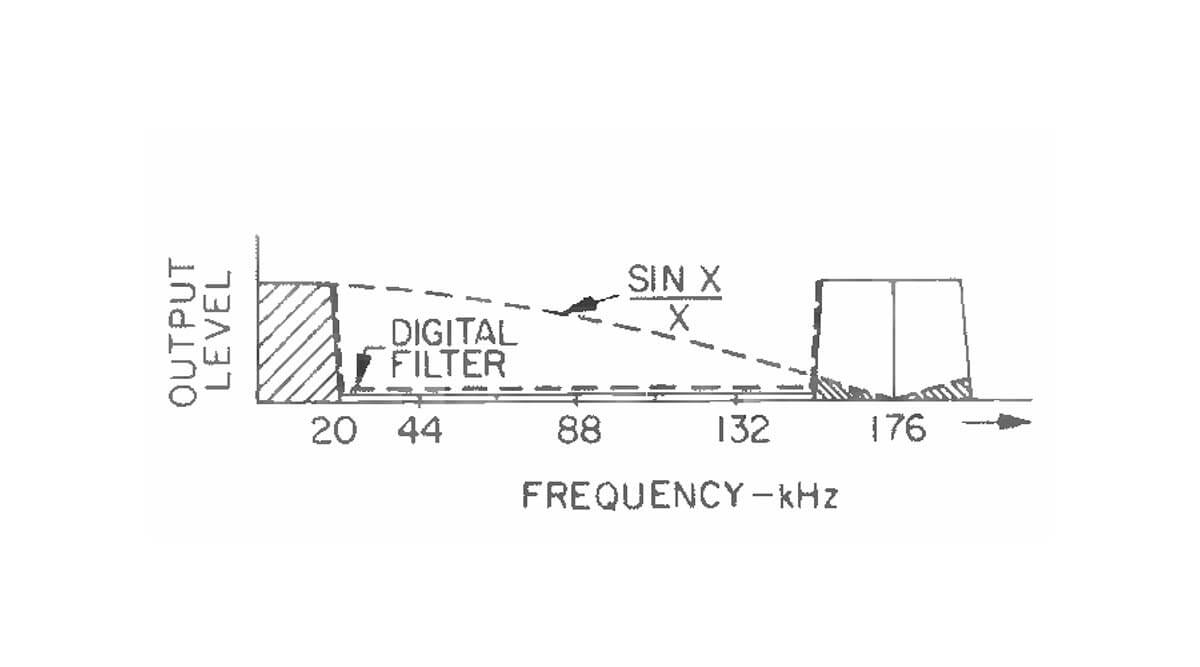 Fig. 9 - Output spectrum of oversampling D/A converter before analog filtration.
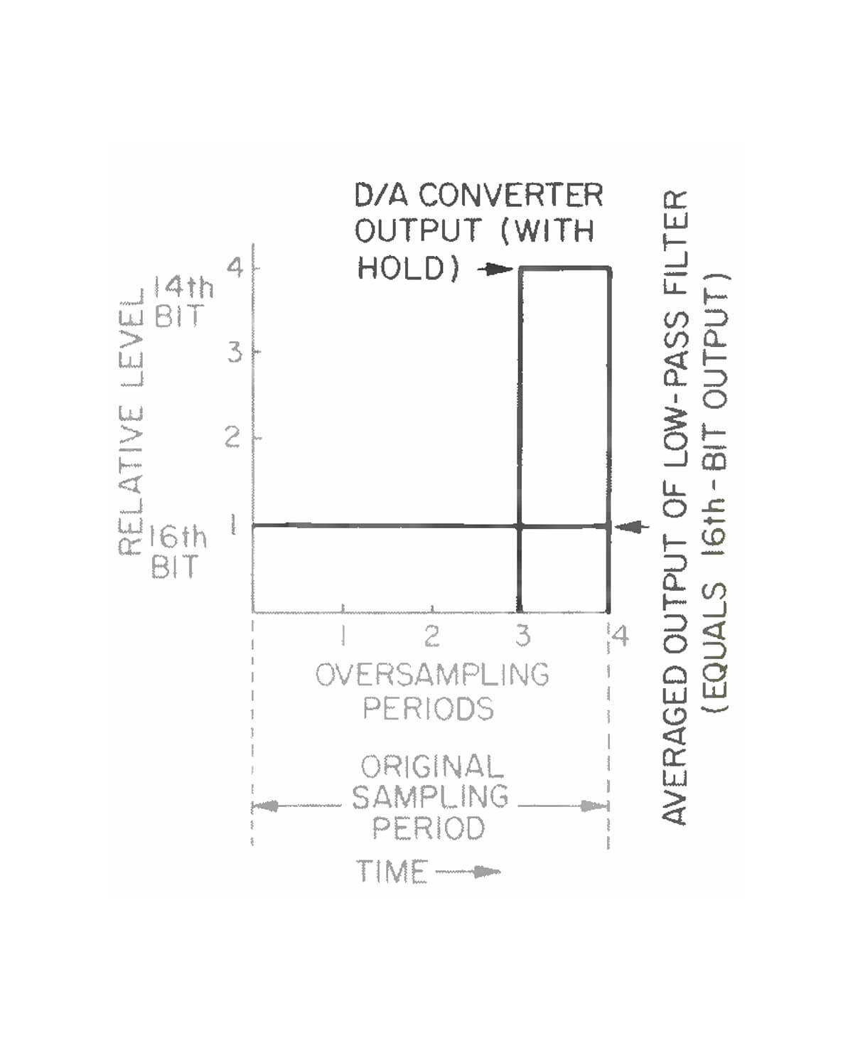 Fig. 10 - How average of one 14 -bit sample and three null samples match accuracy of a single 16 -bit sample over the same period.
This attenuation, however, is still not sufficient to attain the desired 50 -dB or greater overall reduction of spectral components outside the audio band. Alow-pass, third -order Bessel filter isused to remove the remainder of these ultrasonic frequencies. This filter has its -3 dB point at 30 kHz and was chosen because it has a linear phase characteristic. The Bessel filter and the hold function cause a slight attenuation at the high audio frequencies;this is compensated for in the design of the transversal filter, which has a slightly rising characteristic just below cutoff.
The 14 -bit output from the noise -shaper circuit allows the use of 14 -bit D/A converters. These, unlike current 16 -bit converters, can be made very stable, linear to within one-half the value of the least -significant bit, over a wide temperature range of -20° to+ 70° C.+
The full 16 -bit information capability of the Compact Disc is retained in this Philips system because the information is transferred into the 14 -bit level. This phenomenon is possible because the signal and residual noise of the system combine to produce duty -cycle modulation of the 14th bit. If we look at the average value of four quarter -length 14th -bit samples, three of which are actually null, we find that this average is just as accurate as the full-length, 16th -bit sample for the same period (Fig. 10).
We can thus summarize the advantages of the Philips digital -to -analog conversion system as follows: True 16 -bit performance for both signal and noise, linear amplitude response (±0.3 dB, 20 Hz to 20 kHz), linear phase response (± 0.5°, 20 Hz to 20kHz), signal-to-noise ratio greater than90 dB, total harmonic distortion less than 0.005% at 0 -dB level, and excellent temperature and component -tolerance sensitivity characteristics.