Since its introduction in 1984, our second-generation fourchip set for CD decoders (Ref.l) has won the acclaim of player manufacturers and listeners alike for the quality of the sound it can reproduce — for example, see Refs 2 to 6. With this chip-set, the first to make full use of the errorcorrection capability of the CD systems Cross-Interleaved Reed-Solomon code, and the first to discriminate between the errors on a disc (for more reliable corrections), sound reproduction reached levels of fidelity that even surpassed those available with our first-generation circuits.
Philips third generation decoding ICs for CD players - 1988
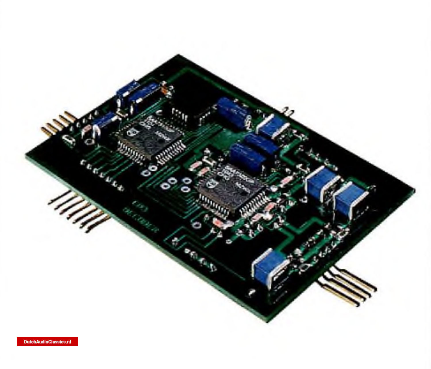 Laboratory model of a complete Compact Disc decoder using the SAA7310 and SAA7320 CMOS circuits
Indeed, the decoding system shown in Fig.1 has become the industry'standard. Whats more, the extremely high level of integration used has reduced the size of the decoding circuitry and the number of peripheral components in a CD player significantly, simplifying board design and lowering assembly costs.
Still higher levels of integration are used in a new CMOS chip set introduced in this article. Intended for use in players in the middle and low end of the market (for example, in audio stacks and portables), this third-generation chip set comprises just two ICs which together perform all the decoding functions and D/A conversion required in a CD player.
 Figure 1 - Second-generation CD decoder
 Figure 2 - Third-generation CD decoder
Besides retaining many of the benefits of our secondgeneration circuits, the new chip set:
- operates from a single (+5 V) supply
- consumes less power
- has an extended operating temperature range (-40 °C to +85 °C)
- has improved facilities for concealing data lost as a result of large external knocks, as commonly encountered by car players and portables. So there is less muting of the audio and hence fewer audible clicks.
- has a software-controlled inhibit of the data interpolation circuitry for CDI and CD ROM applications.
- has improved digital filtering (128 taps instead of 120).
Figure 2 shows the new decoding circuits. The SAA7310 (Ref.7) performs the same functions as the SAA7210 — demodulation, full error-correction, and basic interpolation of uncorrectable audio samples. In addition, it controls the new data interpolation inhibit and the data concealment procedure.
The SAA7320 (Ref.8) includes a phase-linear digital low-pass filter, two new-design high-linearity DACs and operational amplifiers for analogue post-filtering. The level of integration in the SAA7320 is the highest of any current CD circuit. Like the SAA7220 digital filter IC, the SAA7320 has facilities for attenuating the audio output by 12 dB, which can be used at the start of 'fast forward/fast reverse' commands and a search for a track, for example. In addition, the soft mute facility which can be used when moving to another track and during pauses is retained.
The data format between the SAA7310 and SAA7320 is according to the I2S (inter-IC sound) specification*, which allows combinations of second and third-generation ICs (such as the SAA7310, SAA7220 and TDA1541) to be used in a player, giving the player manufacturer maximum design flexibility, see Table 1.
* I2S communication is a communication format for digital audio. The I2S bus is a 3-line bus comprising: clock, serial data line, and a control line used to select left and right channel words (Ref.9).
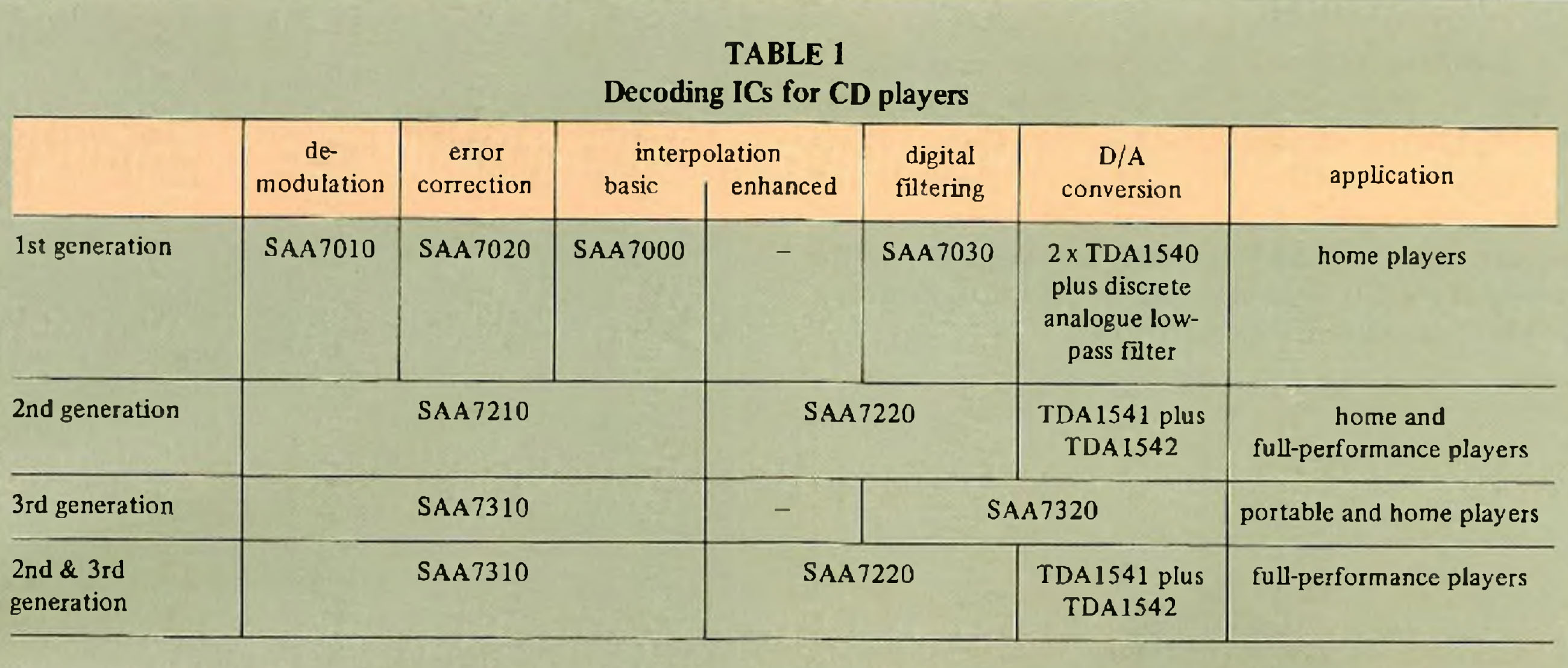 Table 1 - Decoding ICs for CD players
 Figure 3 - Circuit diagram of the third-generation CD decoder shown in Fig.2
Figure 3 is the circuit diagram of a complete CD decoder using the SAA7310 and SAA7320. As the figure shows, the circuit which includes on-chip stereo low-pass filtering requires only a few passive peripheral components.
Philips SAA7310 decoder
The SAA7310 performs all the functions necessary to decode an amplified and filtered version of the EFM (eight-to-fourteen modulated) data stream generated by the pick-up of a CD player. The SAA7310 is available in a 44-pin quad flatpack, or in a 40-pin DIL package suitable for upgrading an SAA7210-based decoding system. The pinning of the DIL version makes the SAA7310 virtually a drop-in replacement for the SAA7210.
All the features of the SAA7210 decoder are retained in the SAA7310, namely:
- fully integrated VCO in the demodulator PLL
- efficient processing ofsubcoding data
- adaptive error-correction
- operates with a large FIFO memory.
These and the new muting facility and selector for nondigital-audio applications such as CDI and CD ROM are summarized below.
Demodulator PLL
The SAA731O's demodulator PLL requires virtually no peripheral components. The VCO is a fully-integrated RC oscillator; it requires no peripheral components. The differential filtering circuitry ofthe PLL uses a self-balancing charge pump design that requires only one filter comprising just three components (Fig.4).
 Figure 4 - In the SAA7310, an integrated charge pump design is used in the differential filter of the demodulator PLL. This filter is self-balanced and consists of only two external components. The VCO is fully-Integrated
Efficient processing of subcoding data
As well as the audio data, Q-channel subcoding data* is derived continually in the SAA7310 from the incoming RF signal. The time spent by the control processor handling subcoding data is reduced by a handshaking protocol between the processor and the SAA7310. When the processor wants data, a request is sent to the SAA7310 which, when a full Q-channel frame is ready, acknowledges the request and enables the Q-channel serial data output. The processor sends a clock signal to shift the data out of the SAA7310.
* Besides the audio information recorded on a compact disc, information representing track numbers and playing times is recorded so that tracks can be played in any desired sequence and titles and elapsed playing times etc. can be displayed. This information is termed Q-channel subcoding data
The first negative-going edge of the clock signal resets the acknowledge signal thereby releasing the request line. If the processor doesn't require all the subcoding data, say only the number of a track (contained in the first sixteen bits), it can reset the request line after these bits have been received, thereby disabling the Q-channel output of the SAA7310 which resumes collecting new subcoding data.
Adaptive error-correction
The CD systems Cross-Interleaved Reed-Solomon Code (CIRC) enables up to four erroneous symbols** (in a 32-symbol block) to be corrected if the CIRC decoder is given prior information about the position of the errors. This type of correction, where the position of an error is known, is called an erasure correction. When the positions of errors are unknown, up to two erroneous symbols can be corrected. A decoder with the maximum error-correction capability (like that of the SAA73I0 and the SAA7210) can make the corrections shown in Table 2.
** 14 bits
Error-correction posibilities of the CIRC decorder of the SAA7310 |
||||||
| e = 0 | e = 1 | e = 2 | e = 3 | e = 4 | ||
| t corrections * | t = 0 | ● | ● | ● | ● | ● |
| t = 1 | ● | ● | ● | |||
| t = 2 | ● | |||||
For optimum error-correction, only the following corrections of Table 2 are relevant:
- t = 2 - Look for and correct two errors, positions unknown
- e = 1, t = 1 - make one erasure correction, and look for and correct one additional error
- e = 2, t = 1 - make two erasure corrections, and look for and correct one additional error
- e = 3 - make three erasure corrections
- e = 4 - make four erasure corrections.
In the SAA7310, adaptive error-correction discriminates between the errors found on a compact disc. This discrimination:
- Enables more corrections to be made (for example, longer burst errors)
- makes the corrections more reliable.
As shown in Fig.5, these improvements are made by using additional error flags generated by the EFM decoder (using the bit run-length criteria to flag symbols likely to be in error) and by using multi-level error flags generated by the C1 and C2 corrector*.
* Two Reed-Solomon codes Cl and C2 are used to correct erroneous audio samples, Cl being used to correct random errors in adjoining symbols, C2 to correct burst errors.
With the error flags, several error-correction strategies are available, the strategy chosen depending on the type and number of error flags which are set by the defects on a disc.
Extensive testing with discs has shown that error-correction is significantly improved by using multi-level flags to signal symbols in error, three flags (two bits) being sufficient:
- Hard error-flag (most reliable flag)
- medium error-flag
- soft error-flag (least reliable flag).
A no-error flag is indicated by setting both bits to zero.
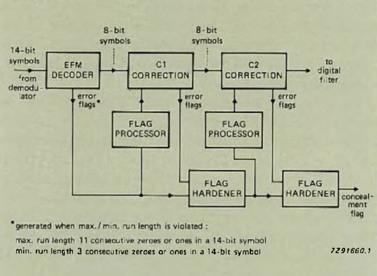 Figure 5 - Symbols that violate the run length criterion are flagged 'likely to be in error' by the EFM (Eight-to-Fourteen Modulation) decoder. With this advance information, the C1 corrector can correct up to four erasures (symbols in error whose-position is known). Although shown here as two correctors. C1 and C2 is a single corrector using sequential processing with the FIFO memory as buffer for de-interleaving 32-symbol blocks of data
With these flags, the best correction strategy is selected by a flag processor, see Fig.5. For example, when two symbols in a block of thirty-two are flagged with soft errorflags, it is best to attempt a t.= 2 correction (rather than an e = 1 and a t = 1, or an e = 2, t = 1 correction). When two symbols are flagged with hard flags, it is usually better to attempt an e = 2 correction and to look for and correct another symbol in error with the remaining t = 1 capability. After a correction, the input flags are compared with the new flags produced by the corrector to update (harden) the flags for the next stage of processing. Flag hardening progressively improves the reliability of all flags, so that very reliable e = 3 and e = 4 corrections can also be made.
All the error-corrections routes (about 60) for CD audio applications are programmed in ROM in the SAA7310.
Large FIFO memory for car players and portables
Part of the memory used to de-interfeave the error-correction data is used as a FIFO memory to remove variations in the demodulated-data rate due to, amongst other causes, the g-forces on car players and portables. In addition, this FIFO can be used to increase the allowable mechanical tolerances for the disc drive of a player. The SAA7310 is designed to operate with a 16K4 DRAM which can accommodate up to 64 frames. The FIFO is also used to store the increased number of error flags used in adaptive error-correction.
Additional mute
This feature was not incorporated in the SAA7210. Designed to improve the performance of car players and portables in particular, it enables the SAA7310 to reconstruct missing data when tracking is lost as a result of a severe knock to a player.
Should track loss occur, taking the 'additional mute' pin (AM) of the SAA731O LOW forces the data stream LOW before it enters the FIFO memory, that is, before de-interleaving, and the data is flagged as being in error. In general, the lost data can be reconstructed by the error-corrector or (after de-interleaving) by the interpolation circuitry, thus preventing any audible clicks in the audio signal. In the SAA7210, only a hard mute is available for use during track loss. This hard mute is retained on the SAA7310 (MUTE pin), but is not required in designs using the SAA7320 digital filter.
The additional mute circuitry can be controlled as the player designer wishes. One way is to use the TL track loss signal generated by our TDA5708 photodiode signal processor.
Digital audio, CDI and CD ROM selector
Another new feature of the SAA7310 is a mode selector (DINT2 pin) which prevents data being interpolated when the SAA7310 is used in CDI and CD ROM applications. For CD audio equipment, the DINT2 pin should be tied HIGH so that any uncorrectable audio samples from the error-corrector are reconstructed by a hold and interpolation circuit (see Fig.6), For CDI and CD ROM equipment, the DINT2 pin should be tied LOW to inhibit this concealment circuit.
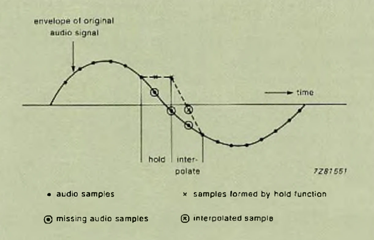 Figure 6 - Example of the hold and interpolation function of the SAA7310
SAA7320 digital filter and DAC
The type of low-pass filter in a CD player influences the quality of the sound reproduced significantly. To create true high-fidelity sound with no detectable colouration, our chip sets for Compact Disc players have, from the outset, used predominantly digital (FIR) filtering with four-times oversampling followed by low-order analogue filtering. The benefits of tliis approach are well-known:
- linear phase response (at a much lower cost than with all-analogue designs, and with no component adjustments necessary)
- fiat pass-band
- optimum roll-off for excellent impulse response
- low noise
- long-term stability (no component ageing effects)
- smaller filter than discrete analogue designs
In the SAA7320, there is again a four-times digital oversampling filter, now followed by another oversampling filter and a noise shaper which simplify the design of the digital-to-analogue converter — now a 1 -bit converter operating at 11.2 MHz and providing 16-bit resolution, see Fig.7 and Ref.10.
The SAA7320 is available in a 44-pin quad flatpack.
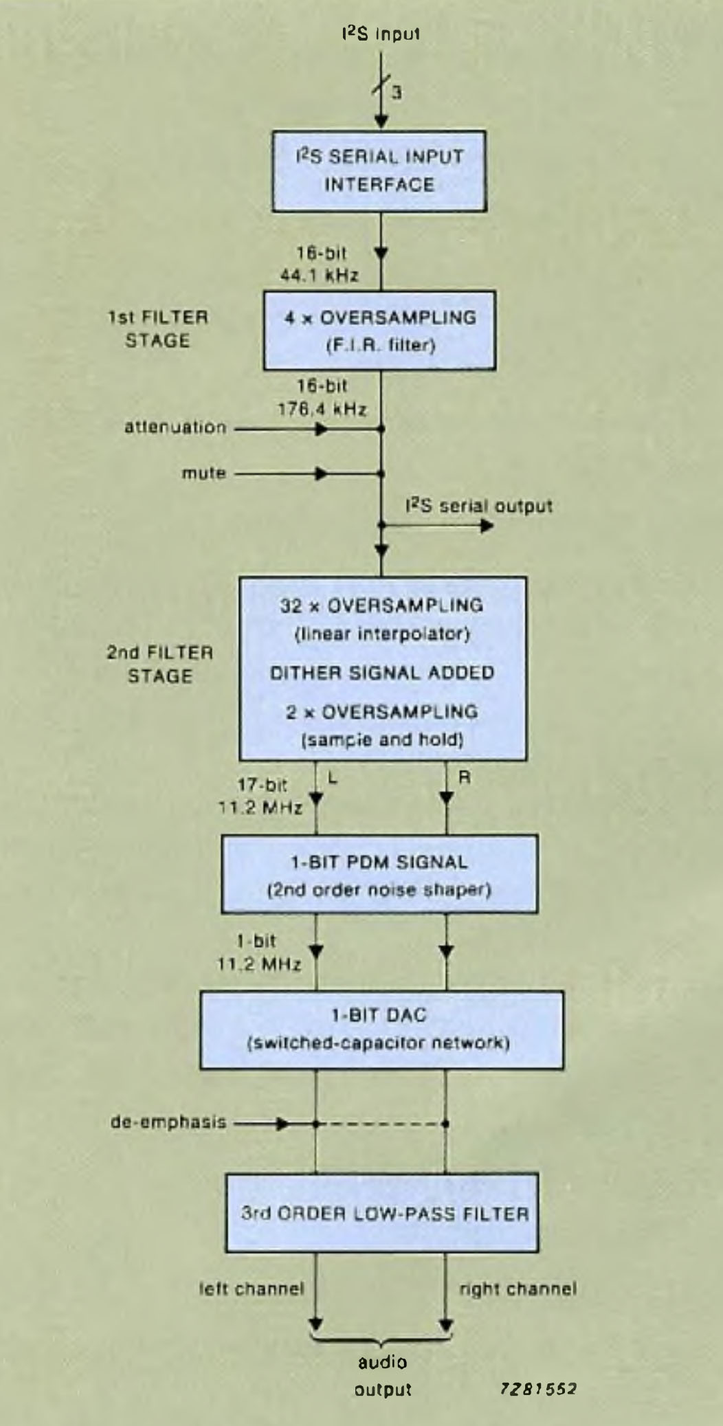 Figure 7 - Data flow of the SAA7320
 Figure 8 - (a) Pass-band characteristic of the two-stage digital oversampling filter and (b) stop-band characteristic of the complete low-pass filter comprising digital filter, noise shaper and analogue postfilter
Digital oversampling filter
The 44.1 kHz sample rate of the 16-bit PCM input words is quadrupled in the first oversampling section of the SAA7320 — a finite impulse response (FIR) low-pass filter with 128 taps (eight more than the digital filter of the SAA7220). The filter has a 20 kHz bandwidth, a pass-band ripple of ±0.02 dB and a stop-band rejection of 60 dB above 24 kHz.
The second oversampling section is an interpolating filter based on an adder structure. The sample rate is increased another 64 times by the combination of a linear interpolator (32-times oversampling) and a sample-and-hold circuit (2-times oversampling). An internally generated outof-band dither signal is used to prevent audible idling patterns of the noise shaper (see next section) at low input signal levels. The amplitude increases because of the dither signal, so an extra bit is needed, making the word length at the output of the linear interpolator 17 bits.
The frequency response of the digital filter contains compensation for the (sin x/x)2 roll-off due to the interpolator (—0.38 dB at 20 kHz) plus the roll-off due to the analogue post-filter (Butterworth characteristic). Figure 8 shows the contribution of each part of the filter to the complete frequency response. Owing to the digital oversampling filter, the analogue post-filter can be of simple design. Furthermore, because the SAA7320 has an I2S output, it's possible to use only the four-times oversampling filter, leaving the design of the remainder of the player completely open.
Noise shaping and D/A conversion
In linear PCM audio systems such as Compact Disc Digital Audio, the noise spectrum of the digital audio samples can be reshaped to decrease the in-band quantization noise when the signal bandwidth is less than half the sampling rate, fs (Ref.l 1). In the SAA7320, the use of oversampling, which spreads the noise over a wide bandwidth, and of noise shaping techniques lowers the in-band quantization noise to that,equivalent to 16-bit resolution, from a 1-bit DAC operating at a sample rate of 256fs (11.28 MHz).
The input signal for such a DAC is derived by passing the 17-bit oversampled and digitally-filtered PCM words through a quantizer which reduces the word length to 1 bit. A loopfilter that feeds the quantization error back to the input of the quantizer reshapes the 1-bit quantization noise, leaving only a small portion of this noise in the audio band.
As can be seen in Fig.9(a), the circuit of the 1-bit DAC is very simple. Its function is to modulate a DC voltage with the 1-bit data stream and the circuit is implemented using a switched-capacitor network. Figure 9(b) shows the timing diagram. During the first half of the sample period, either CI is charged by drawing a unity charge out of the summing node of the output opamp, or capacitor C2 is discharged by pushing a unity charge into the opamp. During the second half, Cl and C2 are discharged and charged respectively.
The linearity of this type of 1-bit DAC can be better than that of conventional DACs. This is partly because there is only one converter stage instead of many different stages (as in weighted-resistor or R/2 ladder designs, for example), so there is less dependence on component tolerances. In addition, this type of 1 -bit converter doesn't suffer from the LSB inaccuracies of conventional 16-bit DACs, the main component of distortion at low signal levels, see Fig. 10.
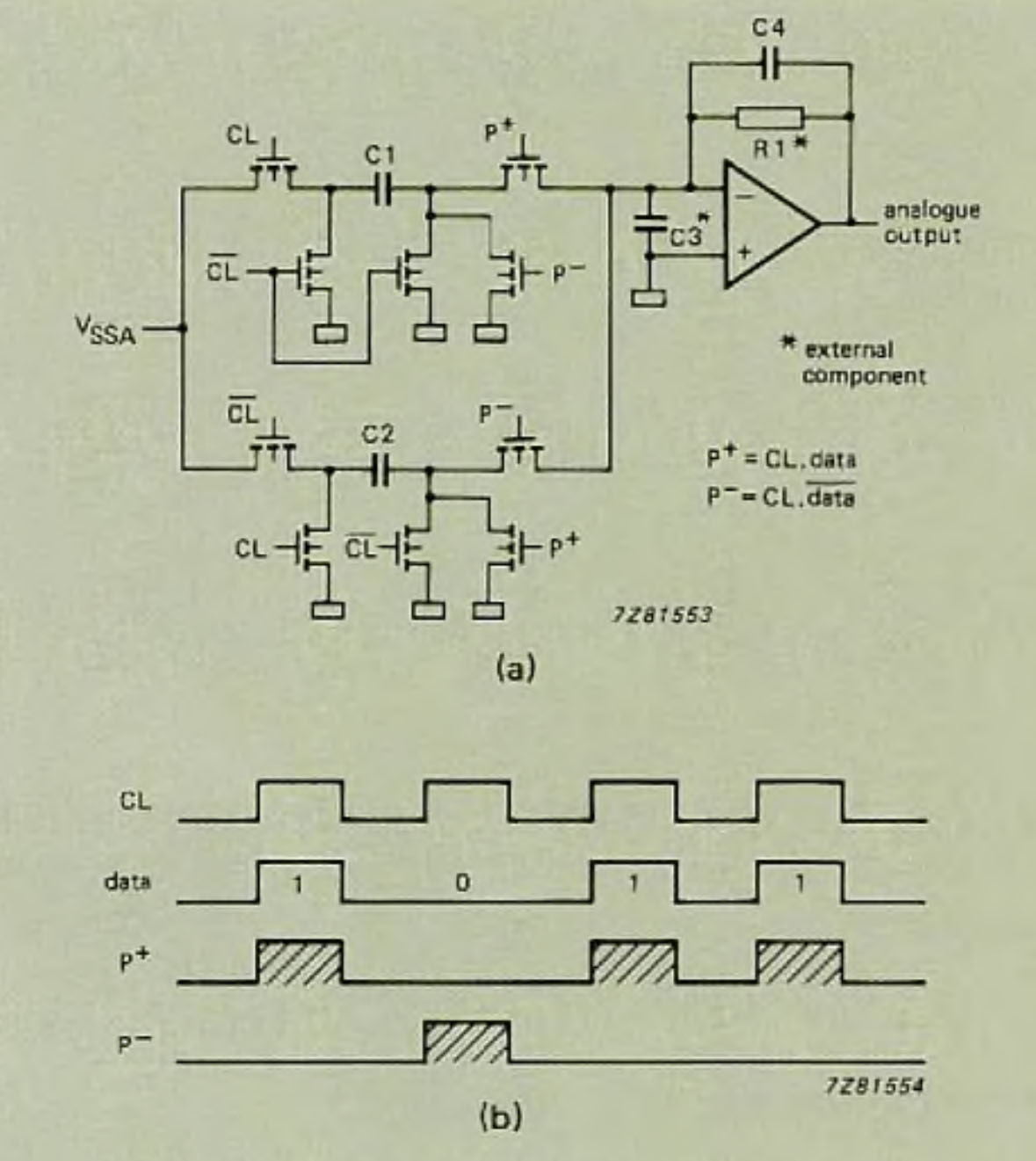 Figure 9 - One-bit digital-to-analogue converter (a) circuit; (b) timing
Analogue post-filtering
In the SAA7320, two operational amplifiers per channel perform analogue post-filtering and current-to-voltage conversion. One opamp is used for the switched-capacitor network (and for some post-filtering), the other is used only for second-order post filtering. The main features of these opamps are high DC gain (90 dB), high slew rate (30 V/μs), and a low 1/f noise figure of-104.1 dB (relative to 0.7Vrms).
For a flat frequency response, the filter section should be a third-order low-pass filter with a —3 dB cut-off at 60 kHz.
There is also a de-emphasis control input in the integrator stage so that the roll-off of the first filter stage can be changed by switching in an extra (external) feedback network when required.
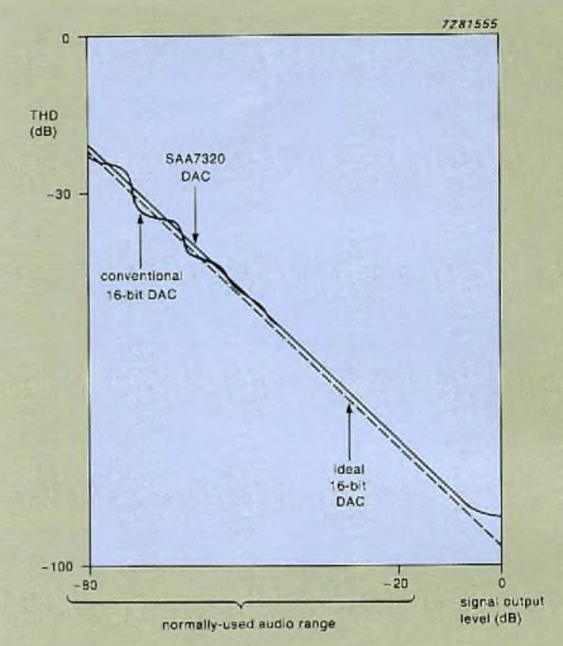 Figure 10 - Superior linearity at low signal levels is one advantage of the SAA7320's 1-bit DAC over a conventional 16-bit DAC. In addition, a compact design allows two of the new DACs (two for stereo), the digital filter circuitry and the opamps of the analogue filter to the integrated on one chip
References
- 'An integrated approach to CD players' Part 2: The decoding electronics. Electronic Components and Applications, Vol. 6 No. 4 1984, ordering code 9398 704 30011. Available as an offprint: Philips Elcoma Technical Publication 172, ordering code 9398 049 60011.
- 'Sweet Sixteen', Which Compact Disc & Hi-fi for Pleasure, July 1986,pp. 69 &77, Spotlight Publications.
- 'A bit more than you can chew', What Hi-fi, August 1986, pp. 85-87, Haymarket Publications.
- 'The definitive players', Which CD & Hi-Fi for Pleasure, August 1986, pp. 46-49, Spotlight Publications.
- 'Sweet Sixteen', Hi-fi News & Record Review, August 1986, pp. 57-61, Newstrade Link Publications.
- 'Walking tali', New Hi-fi Sound, August 1986, pp. 52-55&57, Haymarket publications.
- SAA7310 CMOS decoder for compact disc systems, Philips Elcoma data sheet, 1987, ordering code 9397 147 80142.
- SAA7320 Stereo CMOS DAC for compact disc digital audio systems, Philips Elcoma data sheet, in preparation.
- I2S bus specification, Philips Export B.V., 1986, ordering code 9398 332 10011.
- 'A CMOS stereo 16-bit D/A converter for digital audio', NAUS, P. J. A., DIJKMANS, E. C., et al.; IEEE Journal of Solid-state Circuits, Vol. SC-22, No.3, June 1987.
- Theory and Application of Digital Signal Processing; RABINER, L. R. & GOLD, B., Prentice-Hall, 1985.
Source: Philips Electronics components & applications. VOL. 8 NO. 3. August 1988